


<< T | T-VASIS | T visual approach slope indicator system >>
Back to: "T"
T-VASIS
- Usado para
- T visual approach slope indicator system
- Fonte1
- INTERNATIONAL CIVIL AVIATION ORGANIZATION. Annex 14 to the Convention on International Civil Aviation. Aerodromes. Volume I: aerodrome design and operation. 6th ed. Montreal, 2013.
- Nota adicional1
- The T-VASIS shall consist of twenty light units symmetrically disposed about the runway centre line in the form of two wing bars of four light units each, with bisecting longitudinal lines of six lights, as shown in Figure 5-17. (…) The light units shall be constructed and arranged in such a manner that the pilot of an aeroplane during an approach will: a) when above the approach slope, see the wing bar(s) white, and one, two or three fly-down lights, the more fly-down lights being visible the higher the pilot is above the approach slope; b) when on the approach slope, see the wing bar(s) white; and c) when below the approach slope, see the wing bar(s) and one, two or three fly-up lights white, the more fly-up lights being visible the lower the pilot is below the approach slope; and when well below the approach slope, see the wing bar(s) and the three fly-up lights red. When on or above the approach slope, no light shall be visible from the fly-up light units; when on or below the approach slope, no light shall be visible from the fly-down light units.
- Português
- T-VASIS
- Imagem
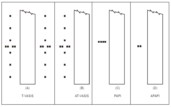
Siting of light units for T-VASIS.
Source: INTERNATIONAL CIVIL AVIATION ORGANIZATION. Annex 14 to the Convention on International Civil Aviation. Aerodromes. Volume I: aerodrome design and operation. 6th ed. Montreal, 2013.